What Do All Those Instructions Do?
So far we've used a few instructions (MOV, ADD, OR, INT, RET), but Intel boasts that their Pentium has HUNDREDS of them. It looks like there's an awful lot to learn.
Actually it's not nearly as bad as it seems. Half of the instructions are very rarely used. You can forget about them for now. The remaining instructions can be classified into groups to make them easier to learn.
Print yourself a copy of PCASM.TXT. It's a reference summary of all the instructions in the PC processor family up through the 80386 including the 80387 math coprocessor (or Floating Point Unit - FPU).
The '486 and Pentium only add about a dozen instructions not on the list, and they are rarely used. The Pentium Pro and AMD Athlon add several sets of instructions such as MMX, SIMD and 3DNow! We'll worry about those in another article.
A very useful document that describes the instruction set is the Microsoft Assembler Reference.
Let's learn some more instructions by looking at another example. So far we've seen how to display single-digit numbers. It would be nice to handle something a little bigger.
DECOUT.ASM contains a routine that displays the value in the AX register as a signed, 16-bit decimal (base 10) number. This enables us to deal with numbers in the range -32768 up through +32767. (If you prefer, you can enter the routine at the label "do10", and it will display an unsigned number in the range 0 through 65535.)
        decout: test    ax, ax          ;if the number is negative then
                jns     do10            ; (jump if not)
                 neg    ax              ; make it positive
                 push   ax
                 mov    al, '-'         ;display a minus sign
                 int    29h
                 pop    ax
        do10:
        do15:   mov     bx, 10          ;ax/10
                mov     dx, 0
                div     bx              ;ax:= dx:ax / bx; dx:= remainder

                push    dx              ;save remainder on stack
                test    ax, ax          ;if the quotient > 0 then
                je      do20            ; (jump if not)
                 call   do15            ; display it as a decimal number
        do20:                           ;  (recurse)
                pop     ax              ;retrieve remainder
                or      al, '0'         ;convert it to ASCII
                int     29h             ;display it
                ret
If you look at your reference sheet, PCASM.TXT, you'll see that the TEST instruction is in the same class as the ADD and OR instructions. TEST does a bitwise AND operation, but it does not store the result. However it does set the status flags (o s z a p c). TEST is used in our example in two places to set the status flags according to the value in the AX register.
The second instruction is JNS (Jump if No Sign). This jumps to the label "do10" if there is no sign (s) bit. In other words, if AX is positive the next few instructions are skipped. If AX is negative then the jump is not taken and the NEG instruction is executed.
NEG negates the value in AX. In our case it converts a negative number into a positive one.
The PUSH instruction temporarily saves our number in AX onto the "stack". This is done because we need to use the AL register to display a minus sign.
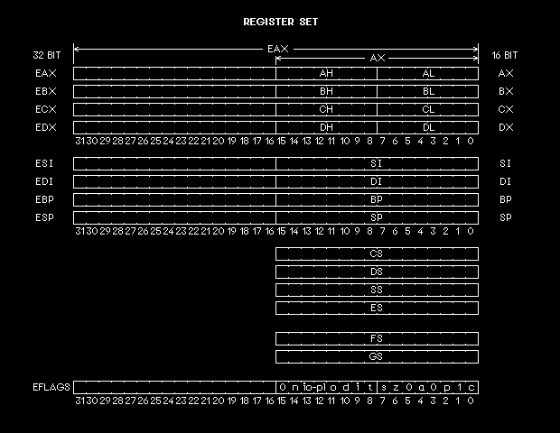
It's time to take a look at the register structure of the PC. From the perspective of an assembly language programmer, the following diagram is pretty much what a PC looks like. The AL register is just the low 8 bits of the AX register, which in turn is the low 16 bits of the EAX register. With the introduction of the '386, the data registers were extended from 16 to 32 bits. Our discussion here focuses on using the lower 16 bits.
There are eight data registers, six segment registers, and a flag register. The data registers are somewhat interchangeable, but they each have unique characteristics. In particular the stack pointer (SP) register is rarely used to hold data, but instead is almost always used to point to a chunk of memory called a "stack". The stack typically holds 16-bit values; which can be data that are pushed onto it by PUSH instructions, or return addresses that are pushed onto it by CALL instructions or by interrupts.
Continuing with the example, the POP instruction restores the value back into AX that we saved on the stack. (When you write code, make sure there is a POP corresponding with every PUSH.)
Setting the BX register to 10 and clearing the DX register to 0 are done to set up the DIV instruction. Divide is an awkward operation. It not only requires several registers, but it's slow. The 32 bits in the combined registers DX:AX are divided by the contents of BX. The quotient is stored into AX, and the remainder is stored into DX. In other words, the number we want to display is divided by 10.
At this point things get a little clever. We save (PUSH) the remainder, which contains the least significant digit, onto the stack. AX now contains a new number equal to our original number, but with its last digit removed. For example, 12345 would now be 1234, and the 5 would be on the stack.
The next instruction TESTs to see if our number has reached zero, and if it hasn't, the following JE (Jump if Equal zero) instruction doesn't jump but falls to the CALL instruction.
This calls a subroutine (like the INT instruction). Every CALL has a corresponding RET instruction, which returns to the instruction following the CALL. CALL pushes the address to return to onto the stack (similar to the PUSH instruction).
This CALL instruction calls a routine to display the number in AX. But that's our routine! We recurse. 1234 gets divided by 10 to become 123, which on the next call becomes 12, which becomes 1, which becomes 0. The stack contains: 5, 4, 3, 2, and 1.
When AX reaches 0, the JE instruction finally skips the CALL by going to the label "do20". Here we POP the "1" off the stack, convert it to ASCII, and display it (like was done in the 2PLUS3 example).
The RET instruction returns us to the point after the CALL, where the 2 is POPed and displayed. This continues for the 3, 4, and 5, after which the RET takes us back to the original call location, which is the instruction following CALL DECOUT (not shown).
This covers the new instructions in our example. Almost all the instructions you need to write meaningful programs are listed on the first page of PCASM.TXT. In fact you can get by without many of them.
If you haven't already done so, get a copy of the Microsoft Assembler Reference.